

GLOBAL | English
TSURUMI MANUFACTURING CO., LTD.


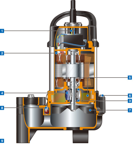
Prevents water incursion due to capillary action should the cable sheath be damaged or the end of cable submerged. Also prevents moist air from infiltrating the motor housing and condensation from forming inside the housing due to temperature differences between the housing and outside air.
Detects excess heat, therefore, protecting the pump against overheating and dry-running.
Directly cuts the motor circuit if excessive heat builds up or overcurrent occurs in the motor.
Isolated in the oil chamber where a clean, non-corrosive and abrasion-free lubricating environment is maintained.
Compared with the water-cooled outside mechanical seal, it reduces the risk of failure caused by dry-heating and adhering matter. The silicon carbide provides 5 times higher corrosion, wear and heat resistance than the tungsten carbide.
Provides lubrication and cooling of the seal faces down to 1/3 of normal oil level, thus maintaining a stable shaft sealing effect and prolonging seal life longer. The Oil Lifter is Tsurumi original design.
This high-purity oil is commonly used in the cosmetics, pharmaceuticals and food processing equipment.
Because it is a food grade lubricant, the pump can be safely used for water features in carp/koi ponds and fish farms.
Enables the motor to be separated from the pump unit with the impeller attached, by removing the bolts between the
oil casing and the pump casing.
This design facilitates maintenance and inspection of the principal parts of the pump.
Resists wear caused by abrasive particles and enables the pump to maintain its original performance for an extended period of time.
Fitted into the pump casing to prevent the air lock. When air flows through the valve, the ball stays at the bottom, but when the pumped water starts to flow, the ball closes the outlet because of its buoyancy.
Prevents scratching of floor surface.
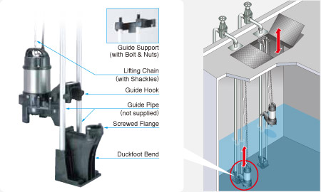
The TOK guide rail fitting system connects the pump to and from the piping easily just by lowering and hoisting the pump, allowing easy maintenance and inspection without the need to enter the sump.
Made of high-quality resin, the TOK is designed for lightweight, small to middle sized pumps.
Rubber bellows attached to the guide hook are inverted to the duckfoot bend when the pump starts operating, and it seals by the pumping pressure. This eliminates leakage at the seal even if a lightweight pump is used in combination with the TOK.
The TOK is available in all motor output ranges of the PU, PN, and PSF series.
The float type automatic model has an integral control circuit and two float switches that operate at a low voltage. It operates automatically in response to the change in water levels.
This model can be identified by the suffix "A" and is available in all motor output ranges of the PU, PN, PSF, and TM series.
The cylindrical float type automatic model is available only for the OM-series.
Adoption of the unique float switch has made even the automatic model very compact and enables it to be installed in a limited space. Automatic operation is possible with a simple power panel.
The auto-alternation model is used along with an automatic model. The combinational use of these two pumps enables each pump to operate alternately without control panel.
The auto-alternation model has three floats and can be identified by the suffix "W".
Refer to model selection for availability and model numbers of the PU, PN, and PSF series.
Water level rises and turns the Float #2 up. The Float #2 is activated but the pump does not start. When water level rises to Float #3 and the float is activated, the "W" unit starts.
The "W" unit is discharging water (Water level falls).
When water level falls to Float #2, the float is activated, and the "W" unit stops. The alternating circuitry deactivates the "W" unit for the next level rise.
If inflow exceeds the capacity of "W" unit and the water level rises to Float #4, "A" unit starts.
The next time the water level rises, Float #1 on the "A" unit is activated but the unit does not start until Float #4 is activated.
The "A" unit is discharging water (Water level falls).
When water level falls and Float #1 is activated, the "A" unit stops. At the same time, "W" unit becomes ready for operation for the next level rise.
If inflow exceeds the capacity of "A" unit and the water level rises to Float #5, "W" unit starts.